Introduction
I remember standing beside a tired machine that had run one part for six hours straight — the operator sighed and said, “We lose minutes every setup.” That scene is common: small shops and big plants alike. CNC equipment manufacturers are hearing the same complaint from customers who want more parts per hour. Recent shop-floor audits show throughput gaps of 12–28% even on newer lines (industry audits, 2024). So I ask: what if the missing gains are not in bigger spindles or faster servo drives but in how we shape and read the cut — the toolpath itself? Let’s unpack that, step by step, and see where real gains hide. Next, I’ll look at where traditional fixes fall short and what that means for your machines.
Why Traditional Fixes Miss the Mark
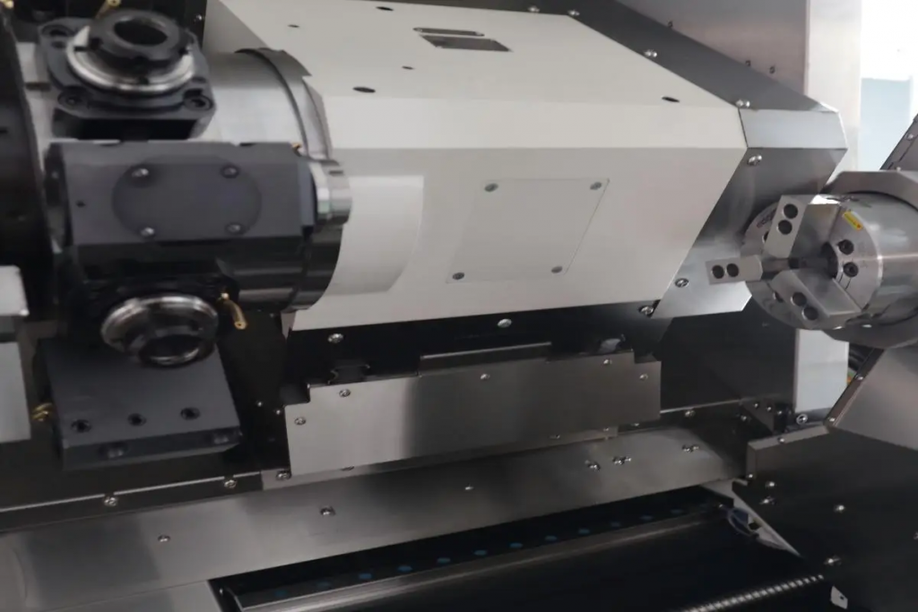
I’ve worked with teams who doubled down on hardware: larger motors, upgraded spindle speed ranges, thicker fixtures. Those moves help, sure. But they often ignore the softer, messier stuff — process friction, poor toolpath optimization, and control latency in the PLC. When I link the problem back to cnc milling equipment, the weak spot shows: programs with inefficient passes, unnecessary retractions, and hand-tuned feeds that never reflect actual torque curves. You can buy the best spindle and still watch chips pile up while one poorly planned toolpath burns time. Look, it’s simpler than you think: tighten the program logic and you free the machine.
So where exactly does it break?
First, the CAM-to-controller handshake is often lossy. Post-processors output generic moves that ignore machine-specific dynamics. Second, operators override feeds without logging why. Third, measures like spindle speed and tool wear live in separate spreadsheets, not in the control loop. These are pain points. We need tighter feedback — edge computing nodes that sample spindle load, smarter toolpath planning that avoids harmonic chatter, and better integration with power converters and servo drives. I’ve seen shops improve cycle time by addressing just one of these items. It’s not glamorous, but it works.
Case Example and Future Outlook
Let me tell you about a mid-sized shop I advised. They sourced a new CAM plugin and trained staff to read live-cut telemetry. Within three months their scrap rate dropped and cycle time fell by 15%. The interesting part: they used a mix of simple fixes and one new principle — adaptive feed overrides driven by spindle torque. This is practical, not science fiction. If you look at manufacturers in asia and europe, many are experimenting with similar setups; some even buy parts from cnc milling machine china suppliers that include basic telemetry out-of-the-box. The point: you can prototype changes fast and learn quickly — funny how that works, right?
What’s Next
Going forward, I expect three shifts. One: tighter CAM-to-CNC feedback loops. Two: more use of small on-machine compute for real-time adjustments. Three: better logging so we can see why an operator modified a program. These moves lower risk and speed learning. I recommend you test one modest change first — swap a static feed schedule for an adaptive routine — then measure. We must pick solutions that are measurable and repeatable.
How I Recommend You Evaluate Options
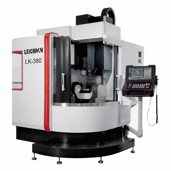
I’ll finish with three concrete metrics I use when judging fixes: (1) Cycle-time reduction percentage — measured across 50 consecutive parts; (2) Scrap or rework rate change — tracked weekly; (3) Operator intervention frequency — how often does someone override the control. These three tell you if a change truly saves money and time. I’ve applied this checklist myself and it keeps conversations honest. If you want a practical partner in testing ideas, consider the tools and support from Leichman. I find their approach straightforward and aligned with what shops actually need.