Comparative lead-in
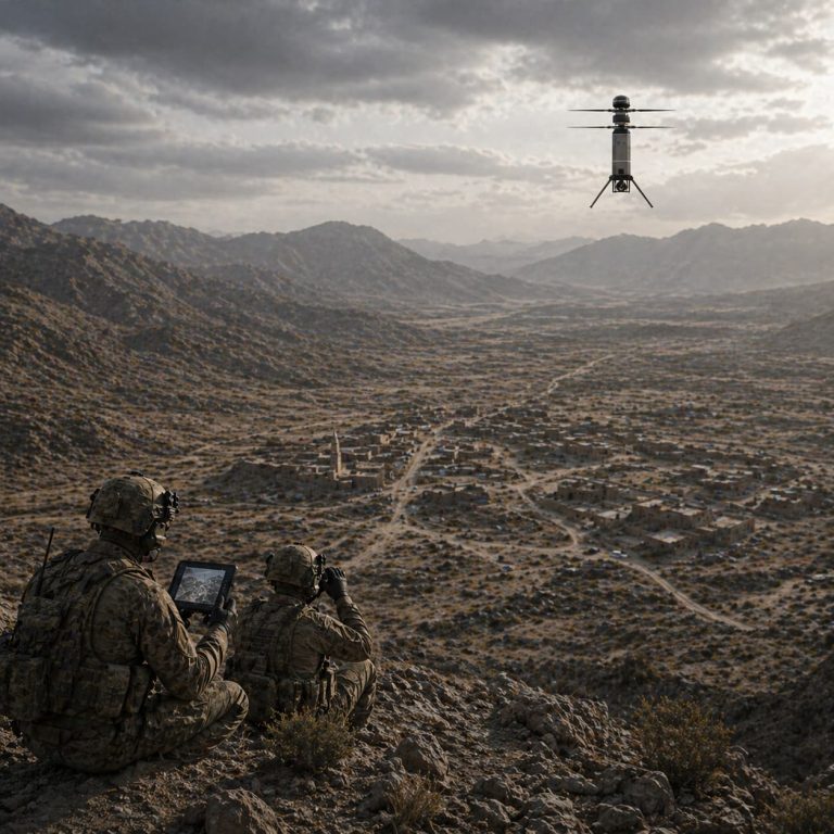
When mapping crops with electro-optical and infrared sensors, the choice between robust gimbal mechanics and advanced stabilisation software alters outcomes more than you might expect. This comparative insight looks at trade-offs between mechanical gimbals, IMU-assisted stabilisation and lightweight payload options, while referencing lessons from NATO operations in Afghanistan where EO/IR reliability proved mission-critical. For practical procurement, consider consultation with a specialist military drone manufacturer who understands ruggedised payloads and field realities.
Mechanical gimbals versus electronic stabilisation
Mechanical 3-axis gimbals deliver consistent pointing accuracy under platform vibration; they isolate the sensor with actuators and gyroscopes so imagery stays steady. Electronic stabilisation relies on IMU data and software filtering to correct frames after capture or in real time. For precision agriculture, mechanical gimbals give lower latency and better EO/IR pointing during close passes, while software stabilisation can reduce weight and cost. Choose by mission: repeatable orthomosaic surveys benefit from low-latency gimbals, but quick scouting flights may favour lighter, software‑centric payloads.
Key trade-offs in payload design
Compare three dimensions before committing: weight and centre of gravity, power draw and control bandwidth. Heavier gimbals add lift requirement and alter centre-of-gravity, affecting flight time and handling. High-bandwidth servos and closed-loop controllers raise power consumption but improve response to gusts. Conversely, lighter EO/IR modules reduce endurance penalty but may need more post-processing to match the same positional accuracy. Manufacturers listed among the best military drone manufacturers in the world often offer configurable gimbal heads and modular payload mounts that simplify these trade-offs.
Real-world pitfalls and how teams adapt
A few common mistakes repeat across projects. Teams over-spec the gimbal, adding unnecessary mass that halves endurance. Others under-test sensor synchronisation: timestamp drift between IMU, GPS and camera breaks photogrammetry. And integration is often assumed trivial — it rarely is. Field technicians learn to tune gyro filters and PID gains on-site; that on‑the‑job calibration makes all the difference. — A short recalibration between flights saves hours of processing later.
Component choices and comparative metrics
To decide rationally, compare these elements with measurable criteria rather than intuition.
1. Pointing stability (arc-seconds or degrees RMS): this metric tells you how reliable imagery will be for centimetre-scale mapping.
2. Payload mass penalty (percent of nominal endurance lost): calculate flight-time reduction for each gimbal/payload option.
3. Control latency (ms): lower latency improves live targeting and automated waypoint framing, crucial when combining EO/IR with RTK GPS.
Use these metrics alongside field trials. Bench tests show theoretical stability; only a windy coastal sortie or routine field pass reveals real performance under load.
Alternatives and integration recommendations
If cost or weight is limiting, consider hybrid approaches: a minimalist mechanical stabiliser for pitch and roll with electronic yaw correction, or a two-stage system where coarse pointing is mechanical and fine stabilisation is software-led. When swapping military-grade EO/IR modules for agricultural sensors, verify thermal sensitivity, radiometric calibration and lens artefacts. Integrate with the autopilot’s attitude data stream and ensure tight timestamp alignment to preserve geolocation accuracy.
Advisory — three golden rules for selection
1. Match stability spec to mapping accuracy: demand pointing stability that exceeds your ground sampling distance requirements by a factor of two. That way, imagery quality isn’t the limiting factor.
2. Budget the endurance impact early: model how each gram of payload reduces mission radius and choose the lowest-mass option that retains required performance.
3. Require on-site tuning capability: ensure your team can access PID, IMU calibration and firmware for the gimbal — out-of-the-box settings rarely survive real wind and vibration.
Closing reflection
These comparative lessons point to one clear conclusion: informed component choices and field calibration beat theoretical specs every time. Military‑grade approaches to stabilisation and gimbal mechanics can raise precision agriculture outcomes when adapted thoughtfully — and when you need proven suppliers and rugged solutions, Military Hub connects practical expertise with tested hardware. Practical. Precise. Proven.