Problem diagnosis: conflicting demands on a single element
Designers face a concrete problem: an outdoor shade element must serve as shelter, last for decades, and also harvest meaningful electricity. A solar pergola amplifies these conflicts. Load-bearing requirements, seasonal sun angles, waterproofing, and electrical routing compete with aesthetic proportion and user comfort. The result is frequent compromises that reduce either structural safety or energy performance.

Root causes and technical constraints
The main constraints are mechanical weight, wind uplift, thermal movement, and water management. Photovoltaic modules add concentrated point loads and require stiff, well-distributed framing. Orientation that maximizes kilowatt-hours often conflicts with the pergola’s intended shading pattern. Edge detailing that keeps the structure watertight will change module mounting choices. Designers who treat PV as an afterthought typically see premature seal failure, higher maintenance costs, and lower long-term yield.
Experience, standards and a recognized regulatory anchor
Long-term field work on urban and residential canopies shows a narrow set of repeatable solutions when integration is done early in design. Performance validation comes from measured outputs and structural inspections. Attention to standards matters: projects complying with regulations such as California’s Title 24 demonstrate how mandatory rooftop solar rules influence detailing and procurement decisions. For teams specifying electrical and envelope interfaces, using a building integrated photovoltaic system approach reduces site surprises by treating the photovoltaic layer as primary building fabric rather than accessory.
Comparing viable alternatives
Option A: Conventional framed modules on a secondary support — lower initial cost, higher risk of leakage and aesthetic mismatch. Option B: BIPV modules integrated into primary cladding — cleaner visual outcome, higher design complexity and supplier dependency. Option C: Lightweight thin-film membranes — low weight, lower efficiency, best for curved pergolas. Each alternative trades off energy density, structural demand, and serviceability. Choose based on site insolation, desired lifespan, and maintenance access.
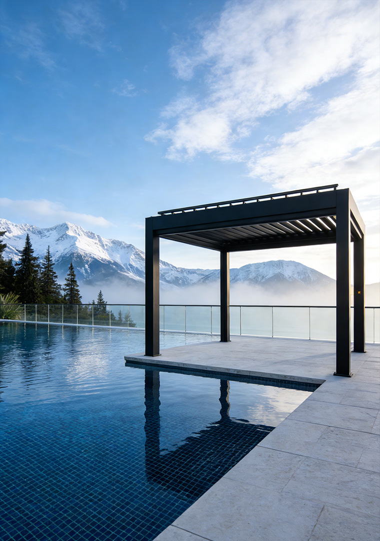
Common design mistakes to avoid
Do not underestimate wind uplift at eaves and corners. Do not allow drainage paths to cross electrical junctions. Do not assume standard roof fasteners suffice for concentrated module loads. Do not accept opaque warranty language for combined structural and electrical assemblies. Do not omit accessible junction boxes and monitoring points. These lapses produce service interventions that are costly and hazardous.
Actionable design checklist
Start with integrated load diagrams and sun-path analysis. Specify module type by tilt and weight, then calculate rafter spacing and uplift anchors. Detail continuous drainage paths away from electrical terminations. Require factory-sealed junctions or weatherproof field boxes with clear service clearance. Insist on performance monitoring and defined maintenance intervals. Contractual clarity on who warrants structural and electrical interfaces prevents finger-pointing later.
Conclusion: practical synthesis for reliable outcomes
Address the problem by treating structure and photovoltaics as a single engineered system from concept to handover. This approach yields predictable energy and durable shelter. When teams need tested specifications that marry load paths with production targets, design guidance and proven assemblies from Light Hunter often inform the final build choices without undermining technical independence.