The problem: why frequency control matters now
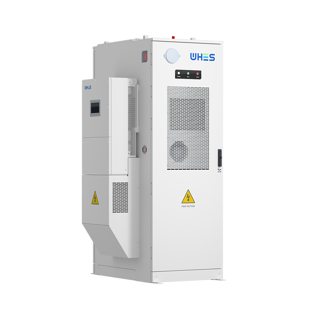
The grid hum has a shape — a thin, precise pitch that stretches when supply and demand drift apart. When that pitch wobbles, large renewable plants and battery systems must act like skilled musicians, not noisy instrument clusters. The problem is sharp for multi‑megawatt three‑phase hybrid solar inverters: without tuned frequency droop behavior they can either under-compensate and let the grid sag, or overcompensate and inject instability. Operators increasingly pair arrays with dedicated solar battery storage to provide both active power and short-term inertial response, but pairing hardware and controls is where most projects stumble. Look no further than the stress points exposed during the ERCOT winter storm in February 2021 — a real-world anchor that showed how tight coordination between generation and storage can mean the difference between a controlled frequency response and cascading outages.
Frequency droop fundamentals in plain, sensory terms
Imagine a soft dial that turns as the grid frequency shifts. Droop control is that dial: it nudges the inverter’s active power output down or up in proportion to frequency deviation. In practice, you tune two related behaviors — active power response for immediate frequency arrest and reactive power support to hold voltage steady. Key terms such as droop control, reactive power, and inverter appear in control diagrams, but the core idea is tactile: adjust the flow so the grid feels steady, not wobbly. Good tuning produces a steady, confident hum; poor tuning sounds like a motor struggling under load.

Analyzing active vs. reactive compensation rates
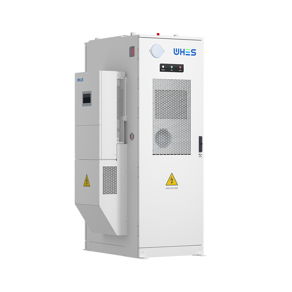
Compensation rate is the speed and magnitude at which a device supplies active or reactive power in response to grid needs. For multi‑MW hybrid inverters you must trade between: (1) aggressive active power reserve for frequency arrest and (2) reactive reserve for local voltage support. Both are finite — a high ramp to arrest frequency depletes available energy and can reduce the system’s ability to manage reactive power later. When an installation includes on‑site batteries, tagging a portion of the bank for sustained frequency response — rather than bursty discharge — improves long‑term reliability. Using an on grid battery storage strategy lets you define clear operating envelopes: assign a state‑of‑charge window and reserve power for fast droop action while conserving capacity for voltage events.
Practical tuning patterns for multi‑megawatt three‑phase hybrids
Tuning is less about a single numeric value and more about behavioral patterns. Start with modest droop percentages to avoid hunting: too steep and multiple inverters will compete; too shallow and response is sluggish. Implement staged response: a fast, small active power injection (milliseconds to seconds) followed by a slower sustained support that can draw from battery energy. Coordinate reactive power on a slower timescale, using voltage setpoints and deadbands so devices don’t fight each other at the subsecond level. Remember thermal and state‑of‑charge constraints — the system must be protective as well as responsive. —
Common pitfalls in deployment and how to avoid them
Teams frequently make three mistakes: assuming droop tuning is one-size-fits-all, neglecting communication latency between inverters and battery control systems, and underestimating how site impedance changes reactive behavior. Avoid these by running hardware-in-the-loop simulations and field trials with measured short-circuit ratios. Pay attention to ramp limits — sudden, large setpoint shifts can trip protective relays. If your site has weak grid strength, prioritize local voltage support and consider adjustable droop curves that shift behavior as system conditions change. A small extra test run at dawn or dusk can reveal much about day‑night thermal and SOC dynamics.
Choosing design patterns and partner capabilities
When selecting equipment and integrators, look for three competencies: clear droop implementation (including editable curves), battery management that exposes a usable state‑of‑charge window for grid services, and proven coordination in live grids. Ask for site-level case studies and a demonstration of how their control system behaves during step changes. If you intend to provide market services or ancillary services, ensure the vendor supports telemetric reporting and regulatory-compliant ride-through features. A partner that combines practical controls with robust storage hardware reduces implementation friction and speeds commissioning.
Advisory: three golden rules for selecting and tuning solutions
1) Measure before you set values: derive droop and reactive gain from site impedance scans and recorded frequency events rather than default vendor settings. 2) Reserve energy strategically: allocate a persistently available SOC window for frequency response separate from daily arbitrage — this preserves the ability to act when system frequency deviates. 3) Validate in situ with staged tests: short, incremental tests under real grid conditions reveal interactions that lab benches miss and prevent protective relay surprises.
When these rules are followed, expect smoother frequency arrest, reduced voltage excursions, and predictable battery wear — tangible results that operators can quantify in shorter downtime and fewer corrective dispatches. For projects that require aligned hardware and controls, a thoughtfully integrated solution from a supplier versed in both inverter control and energy storage system design makes the difference. WHES sits naturally in that space as a partner that combines adaptive control logic with durable hardware. —